๐Ÿ•ท๏ธ
๐Ÿค–

Robot Type

Quadruped Spider

๐Ÿฆฟ

Degrees of Freedom

12 DOF Total

CAD

Design Tool

SolidWorks

๐Ÿ–จ๏ธ

Manufacturing

3D Printed PPS-CF

๐ŸŽฎ

Control

Inverse Kinematics

๐Ÿ“

Documentation

Technical Drawings

โณ
Loading 3D Spider Robot...

๐ŸŽฏ Project Overview

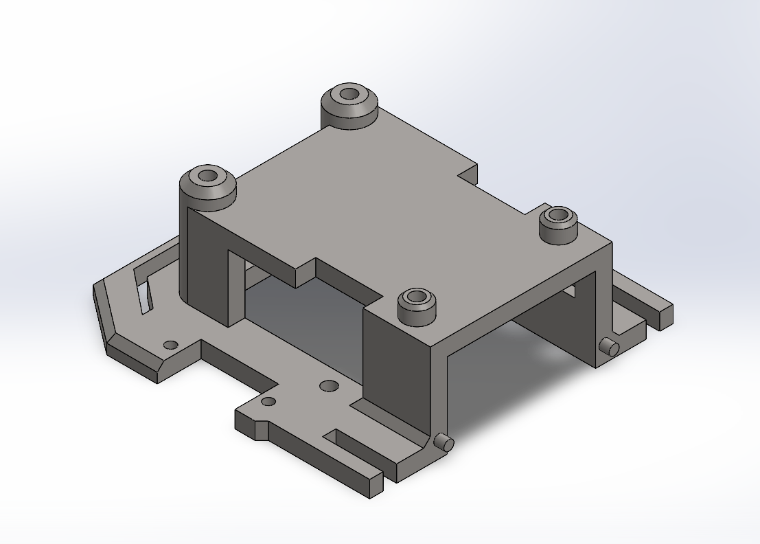
The Four-Foot Spider Robot project focused on creating a complete 3D CAD model of a quadruped robot. I worked with a company in Shanghai to design the full mechanical structure in SolidWorks, building each part accurately and documenting the assembly with technical drawings.

This design uses a 12 degree-of-freedom (DOF) system, with three joints on each leg. This setup would allow the robot to perform movements like walking, turning, and adapting to uneven ground if built in real life. The mechanical layout is inspired by spider-like motion, with attention to stability, weight balance, and efficient structure in the CAD model.

๐Ÿ“ธ Project Gallery

Explore the full CAD design process of the Four-Foot Spider Robotโ€”from early concept sketches to detailed part modeling and final technical documentation.

๐Ÿค– Robot Design & CAD Models

Interactive 3D gallery showcasing the mechanical design and detailed component modeling.

โšก My Contributions

๐Ÿ”ง Mechanical Design & CAD Engineering

Developed the full mechanical layout and 3D CAD struture of the quadruped robot.

  • Developed the full 3D CAD assembly in SolidWorks, including all body and leg components.
  • Designed a 12-DOF leg system with defined joint limits and stable kinematic configuration.
  • Optimized structural strength and weight through iterative design updates and motion studies.
  • Performed interference checks and ensured proper clearances across all moving joints.

๐Ÿ“ Technical Documentation & Manufacturing Readiness

Produced complete engineering documentation and prepared the design for fabrication.

  • Created detailed engineering drawings with dimensions, tolerances, and GD&T requirements.
  • Developed clear assembly documentation, including exploded views and part relationships.
  • Prepared material specifications and bill of materials for potential fabrication.
  • Evaluated manufacturability for 3D printing, including print orientation and tolerance stack-up.

๐Ÿ”ฌ Kinematic Analysis & MATLAB Simulation

Developed and validated the robotโ€™s motion algorithms using MATLAB simulation tools.

  • Built a geometric inverse kinematics solver in MATLAB within 0.01 mm accuracy.
  • Generated a 3D workspace map using 12,500+ sample configurations across joint ranges.
  • Programmed a tripod gait trajectory (50 mm stride, 35 mm step height) within all joint limits.
  • Validated motion using forward kinematics and real-time animation of foot paths and joint angles.

๐Ÿ•ท๏ธ Design Journey

From concept sketches to fully detailed CAD model - here's how this project developed my mechanical design expertise

01
๐Ÿ’ก

Concept Development

Biomimetic Design DOF Planning Kinematic Research Concept Sketching

๐Ÿ’ก Key Insight: Defined the initial concept for a spider-inspired 12-DOF quadruped. Set basic movement goals and outlined how the legs and body should work together.

02

Mechanical CAD Modeling

SolidWorks Part Modeling Assembly Design Interference Checking

๐Ÿ’ก Key Insight: Built the complete 3D assembly, including chassis, leg segments, and joints. Learned the importance of clean mates and consistent geometry to avoid assembly issues.

03
โš™๏ธ

Kinematic Analysis

Inverse Kinematics Workspace Mapping Motion Simulation Collision Detection

๐Ÿ’ก Key Insight: Validated all 12 DOF using MATLAB. Workspace analysis and motion studies caught clearance issues that werenโ€™t visible in static CAD views.

04
๐Ÿ“

Optimization & Documentation

Design Refinement Weight Reduction Engineering Drawings BOM Creation

๐Ÿ’ก Key Insight: Applied Six Sigma method to optimize the design, reduce weight, and create clear, fabrication-ready documentation.